

Address
304 North Cardinal
St. Dorchester Center, MA 02124
Work Hours
Monday to Friday: 7AM - 7PM
Weekend: 10AM - 5PM
Engineered aluminum profiles · Extrusion · Machining · Finishing
Address
304 North Cardinal
St. Dorchester Center, MA 02124
Work Hours
Monday to Friday: 7AM - 7PM
Weekend: 10AM - 5PM

Learn how to design an aluminum extrusion for CNC machining with practical stock, datum, wall thickness, fixture and tolerance guidance.
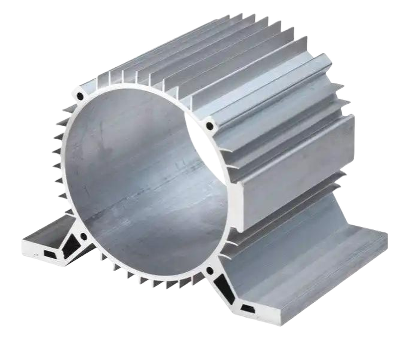
Aluminum Extrusion Design For Cnc Machining is best evaluated as a complete engineering and production decision. Aluminum extrusion design for CNC machining works best when extrusion and machining are treated as one process. The profile establishes material distribution, while machining creates holes, faces and interfaces that cannot be formed by the die.
A profile that looks efficient as a drawing may be difficult to fixture or inspect. Therefore, datum surfaces, clamping access and machining stock should be reviewed before the die is manufactured. The objective is not simply to select aluminum; it is to define a repeatable component that meets fit, thermal, electrical, corrosion and assembly requirements.
Use the following points to turn the application target into a manufacturable specification:
In addition, confirm the critical dimensions with the team responsible for tooling, machining and inspection. For example, a tolerance that works on a drawing may be impractical if the datum cannot be reached during machining.
The manufacturing route should be reviewed before the die, fixture or finish is committed. A practical sequence is:
Therefore, keep the drawing, sample approval, process specification and inspection plan aligned. If one changes, check whether the others still reflect the finished component.
The extrusion should establish the general form, material distribution and repeatable length of the part. CNC machining should establish the bores, sealing faces, cross holes, threads and other interfaces that need tightly controlled position or surface finish. This split keeps the die practical while preventing an expensive secondary operation from being added for a dimension that the profile can hold reliably.
For example, a motor housing may use the extrusion for external fins and the internal stator envelope, then machine the end-face register and bearing bore. Requiring the extrusion alone to control bore roundness or face flatness usually creates tolerance stacking between quenching, straightening, cutting and clamping. Instead, define which surfaces locate the part in the fixture, which surfaces remove stock, and which datum remains accessible after each operation.
Use a consistent datum scheme from the model through first-article inspection. If the primary datum is a narrow flange that the fixture cannot reach, the shop may choose a different surface and create an invisible process variation. A short DFM review should confirm tool reach, clamping pressure, chip evacuation, coolant access and the sequence for machining both ends.
Machining allowance has to cover profile tolerance, straightness, twist, cutting error and the minimum cleanup required by the finish specification. Adding uniform stock everywhere increases weight and cycle time without necessarily solving distortion. Put allowance where a machined surface must clean up, but leave non-functional surfaces as extruded where practical.
Review thin walls beside deep pockets and high-clamp areas as a single manufacturing feature. A wall may meet the extrusion drawing yet deflect during machining because the fixture closes an unsupported section. Adding a temporary bridge, changing a rib or moving a clamping pad can be more effective than tightening every profile tolerance.
Inspection should focus on the characteristics that control fit and function. The exact sampling plan belongs in the approved drawing and purchase specification.
When comparing quotations, ask whether the supplier has priced the extrusion and machining from the same drawing revision. Confirm that the quotation states stock allowance, fixture responsibility, datum assumptions, sampling and the treatment of first articles. A low extrusion price is not useful if the machinist later requests a new die because the locating surfaces cannot be held.
For repeat production, keep a boundary sample and a first-article report that link the profile, machined features and finish. Review any change to alloy, die, straightening route or fixture before production resumes.
This route suits motor housings, electronic enclosures, heat sinks and equipment components that share a constant section but need local machined features.
Useful reference material includes the Aluminum Association extrusion resources, AEC extrusion tolerances and the relevant ASTM B221 product specification. The approved drawing and purchase order still control acceptance.
For a related production route, review machined aluminum housings or HIQ aluminum product families. You can also send the drawing to the engineering team.
Use enough stock to correct straightness and achieve the surface requirement without adding unnecessary weight or machining time.
Holes along the extrusion direction can be formed in the profile, while cross holes and precision interfaces are normally machined.
Yes, when fixture constraints are known early. Otherwise a small change to access or clamping can save significant machining cost.
