
Address
304 North Cardinal
St. Dorchester Center, MA 02124
Work Hours
Monday to Friday: 7AM - 7PM
Weekend: 10AM - 5PM
Address
304 North Cardinal
St. Dorchester Center, MA 02124
Work Hours
Monday to Friday: 7AM - 7PM
Weekend: 10AM - 5PM

Use this aluminum heat sink fin thickness guide from HIQ Aluminum to review design, material, tooling, machining, quality checks and quotation requirements.
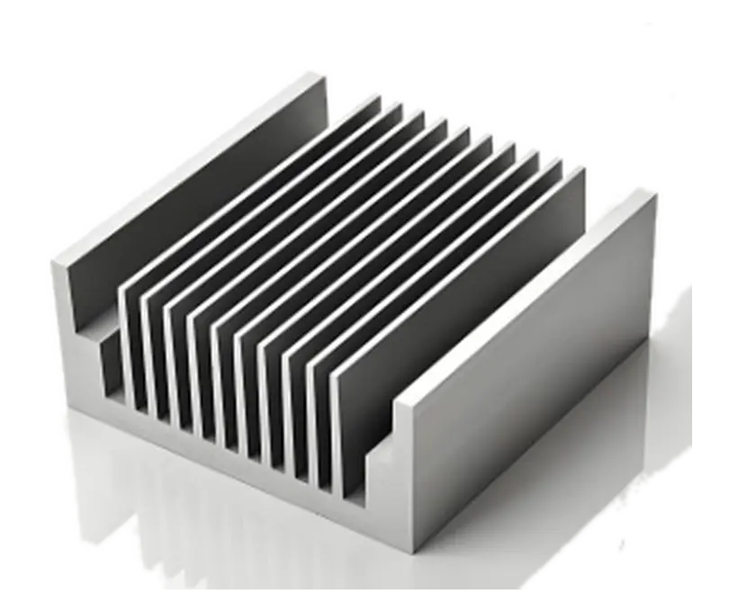
Aluminum Heat Sink Fin Thickness is best evaluated as a complete engineering and production decision. Aluminum heat sink fin thickness affects conduction, surface area, airflow and manufacturing cost. Thin fins can add area, yet they may perform poorly when the airflow is low or the base cannot spread heat effectively.
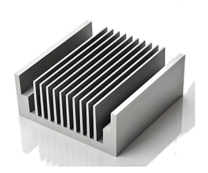
The correct fin thickness is a balance between thermal resistance and tooling reliability. Extrusion adds practical limits because very thin, tall fins can reduce die life and dimensional consistency. The objective is not simply to select aluminum; it is to define a repeatable component that meets fit, thermal, electrical, corrosion and assembly requirements.
Use the following points to turn the application target into a manufacturable specification:
In addition, confirm the critical dimensions with the team responsible for tooling, machining and inspection. For example, a tolerance that works on a drawing may be impractical if the datum cannot be reached during machining.
The manufacturing route should be reviewed before the die, fixture or finish is committed. A practical sequence is:
Therefore, keep the drawing, sample approval, process specification and inspection plan aligned. If one changes, check whether the others still reflect the finished component.
Heat moves from the base into each fin by conduction and then leaves the fin surface by convection and radiation. A thinner fin contains less metal, but its temperature falls more quickly from root to tip. The resulting fin efficiency can offset part of the extra surface area obtained by adding more fins. The useful comparison is therefore the complete heat sink at a defined air velocity, pressure drop and mounting orientation, not fin thickness in isolation.
Fin pitch has an equally strong effect. Closely spaced fins increase area, but they also increase flow resistance and can create a boundary-layer blockage that leaves the middle of the array underused. Natural-convection designs generally need wider passages than forced-convection designs. Dust, altitude and enclosure restrictions can make an apparently efficient dense array perform worse in service.
A small heat source on a large base first has to spread into the base before heat can reach the outer fins. If the base is too thin, the perimeter runs cooler and the calculated total area is misleading. The base also needs enough stiffness and thickness to distribute mounting pressure through the thermal interface without bowing away from the device.
Extrusion tooling adds another limit. Tall, thin fins with sharp roots concentrate die stress and are harder to fill consistently. A small increase in root thickness or radius may improve die life and straightness while causing only a minor thermal penalty. During design, compare at least two practical geometries: one with more, thinner fins and one with fewer, more efficient fins. Test them with the intended fan curve or natural-convection orientation.
Record ambient temperature, heat load, airflow, pressure drop and orientation during testing. Measure both the device case and heat-sink base so that interface resistance is not hidden in the result. A heat sink can meet a room-temperature bench test and still fail in a sealed enclosure where recirculating air becomes warmer over time.
Inspection should focus on the characteristics that control fit and function. The exact sampling plan belongs in the approved drawing and purchase specification.
A useful RFQ defines the thermal target and the mechanical envelope before asking for a price. Suppliers can then propose a manufacturable fin geometry instead of quoting an arbitrary profile. Ask how fin thickness, pitch and straightness will be inspected and how the parts will be packed to protect the fin array.
For repeat orders, avoid changing the extrusion supplier without comparing thermal samples. A visually similar profile can have different wall distribution, alloy conductivity or fin-root geometry and therefore different performance.
This decision affects inverters, power supplies, LED modules and motor drives where the heat sink must fit a compact enclosure.
For material and process context, review the Aluminum Association extrusion resources and ASTM B221. Thermal acceptance should come from the project test plan, because published profile dimensions alone do not predict system temperature.
For a related production route, review aluminum heat sinks or HIQ aluminum product families. You can also send the drawing to the engineering team.
No. Their benefit depends on airflow, fin height and whether the added area can transfer heat efficiently.
Die strength, metal flow, fin height, alloy and tolerance all influence the practical minimum thickness.
Use the lowest-cost profile that meets the thermal target, avoid unnecessary machining and confirm the finish requirement.
