
Address
304 North Cardinal
St. Dorchester Center, MA 02124
Work Hours
Monday to Friday: 7AM - 7PM
Weekend: 10AM - 5PM
Address
304 North Cardinal
St. Dorchester Center, MA 02124
Work Hours
Monday to Friday: 7AM - 7PM
Weekend: 10AM - 5PM

Specify aluminum extrusion tolerances for machining with clear stock allowance, datum plans, straightness, flatness and inspection requirements.
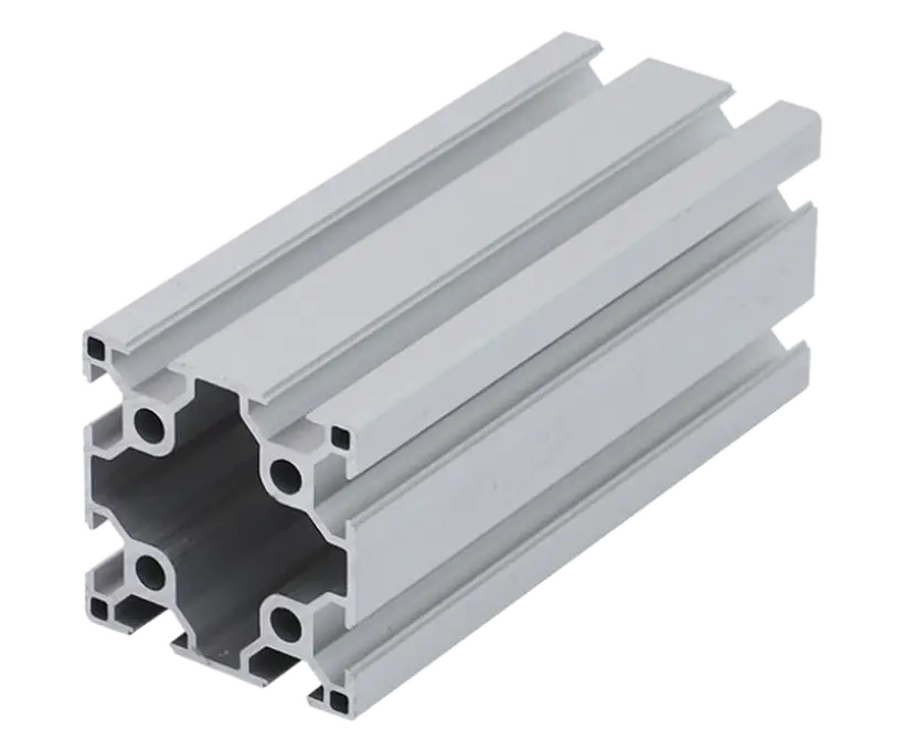
Aluminum Extrusion Tolerances For Machining is best evaluated as a complete engineering and production decision. Aluminum extrusion tolerances for machining should distinguish between the as-extruded condition and the finished machined part. Tightening every profile dimension often adds cost without improving the final assembly.
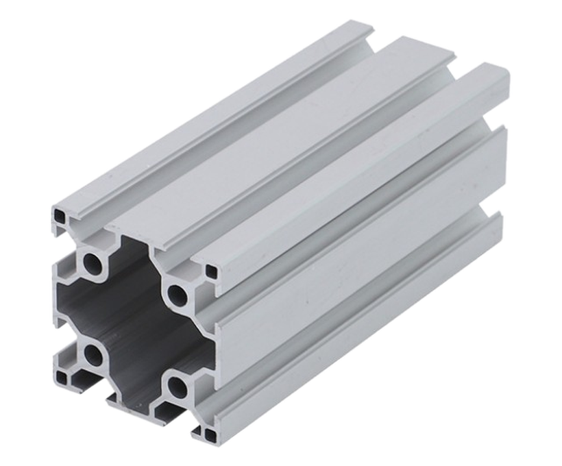
Extrusion tolerance is affected by section size, alloy, wall thickness, quench rate and straightening. Machining then removes variation in selected areas. Therefore, the drawing should state where the extrusion can remain free and where final tolerances apply. The objective is not simply to select aluminum; it is to define a repeatable component that meets fit, thermal, electrical, corrosion and assembly requirements.
Use the following points to turn the application target into a manufacturable specification:
In addition, confirm the critical dimensions with the team responsible for tooling, machining and inspection. For example, a tolerance that works on a drawing may be impractical if the datum cannot be reached during machining.
The manufacturing route should be reviewed before the die, fixture or finish is committed. A practical sequence is:
Therefore, keep the drawing, sample approval, process specification and inspection plan aligned. If one changes, check whether the others still reflect the finished component.
An extrusion drawing normally controls section dimensions, wall thickness, straightness, twist, squareness and cut length. A finished machining drawing controls bores, faces, hole locations and relationships between features. Mixing both requirements into one blanket tolerance note makes the supplier responsible for variation that may be unavoidable in the die or removed later by machining.
A clearer drawing identifies extrusion characteristics that affect handling and stock cleanup, then identifies finished characteristics that must be achieved after machining. Dimensions that can vary with cut length should be referenced to a defined datum. This is especially important for long profiles with twist or bow, because clamping one end can move the other end and change the apparent hole position.
Build the stack-up from the extrusion surface to the fixture, from the fixture to the machined datum, and from that datum to the final interface. If the cutter can reach the surface and the stock is sufficient, the machining operation can usually absorb more variation than the raw extrusion. If the feature is located from an unmachined edge, however, profile variation transfers directly into the finished part.
Use geometric controls where orientation, position or profile matters. A flatness callout on a sealing face describes a functional requirement more clearly than a general dimension. A position tolerance for a bolt pattern relates the holes to a datum frame instead of leaving the inspector to choose an arbitrary reference.
The first-article report should show as-extruded dimensions, straightness or twist, stock before machining, final dimensions, datum setup and surface condition. CMM results without a fixture definition can be misleading. Repeat the critical checks after heat treatment, anodizing or coating if those processes can move or add thickness to functional surfaces.
Inspection should focus on the characteristics that control fit and function. The exact sampling plan belongs in the approved drawing and purchase specification.
Do not buy a tighter general profile tolerance when the real requirement is a precise machined interface. Ask the supplier to separate die capability, machining allowance and final feature tolerance. This usually gives a more realistic price and a process that can be inspected at the correct stage.
Changes in profile size, wall balance or alloy should trigger a review of stock allowance and fixture location. A design that passed with one die is not automatically stable after a die repair or supplier transfer.
The approach is relevant to motor housings, structural profiles, heat sinks and enclosures that require local precision after extrusion.
The AEC extrusion tolerance table, ASTM B221 and the current drawing provide useful context. Regional standards may differ, so the purchase specification should state which edition and tolerance class apply.
For a related production route, review extrusion and machining capabilities or HIQ aluminum product families. You can also send the drawing to the engineering team.
Extrusion alone generally cannot match all machined tolerances. Design critical surfaces for machining and leave the rest within practical profile limits.
Uneven walls cool and contract differently, increasing distortion and making straightness harder to control.
Specify datums, machining stock, critical features, finish, burr limits and inspection requirements.
